Talk:Operational amplifier

 | This  level-5 vital article is rated B-class on Wikipedia's content assessment scale. level-5 vital article is rated B-class on Wikipedia's content assessment scale.It is of interest to the following WikiProjects: | ||||||||||
| |||||||||||


SVG are impossible to see in Dark theme
It seems black lines on transparent background in dark themed viewers causes the lines to be black on black background. 32.221.197.108 (talk) 13:50, 25 May 2025 (UTC)
- Please give an example. Either link to the section (example: Operational amplifier#Positive-feedback applications) or quote some text (example: "Schmitt trigger implemented by a non-inverting comparator"). Johnuniq (talk) 04:18, 26 May 2025 (UTC)
CS1 parameters
I made a recent edit to fix a CS1:maint error. While the fix might not be correct, the previous one is obviously wrong, as it has an error. I am accused of misusing a CS1 parameter. If there is a better one, please use it. But it seems that postscript= is wrong, as it gets an error message. I thought via= was close, but maybe not. Gah4 (talk) 19:11, 21 June 2025 (UTC)
- OK, seems to be fixed now. The postscript= parameters is supposed to be either one character, or the word none. I thought via= was close, but didn't know about id= or series=. Thanks for fixing it, though. Gah4 (talk) 19:22, 21 June 2025 (UTC)
Big deletion of the internal circuitry section
This was discussed a long time ago Talk:Operational_amplifier/Archive_3#Seperate_page_for_the_μA741? and there was no clear consensus to split it. There was though a broad feeling that the section was important and belonged somewhere. Andy Dingley (talk) 00:05, 15 November 2025 (UTC)
- @Andy Dingley Wikiversity, maybe. fgnievinski (talk) 01:13, 15 November 2025 (UTC)
- No, not at all. It's valuable and encyclopedic, and belongs on a site with a readership. Whether that's in this article or in a more specific article on the 741.
- This is not a great article, although it is a broad topic and thus hard to write, impossible to fit into one article. It needs to cover both the internal and external operation of an op-amp, also the history and context as to what an 'op-amp' is in the first place (that's a very poor intro at present). It's a mistake to see the removed section as 'only relevant to the 741'. This is also a useful exemplar for op-amp internal design generally: most monolithic bipolar op-amps follow a similar design, at least at the block diagram level. That's now missing and now there's nothing in the article explaining how the internal circuit works. Andy Dingley (talk) 10:41, 15 November 2025 (UTC)
- It reads like instructional material. A link to Wikiversity or Wikiboks could be left behind. fgnievinski (talk) 21:32, 15 November 2025 (UTC)
- What do you mean by "instructional material" ? As in, in what way is that contradictory to an encyclopedia entry? And if there is some issue there, the solution is to copyedit it, not to blank the only description we have of how an op-amp works internally. We certainly could use some editing here, it's a very verbose description and probably goes into more detail than we need for op-amps (the old question about splitting it into a 741 article). The block diagrams of this circuit are, AIUI, still relevant to the implementation of the majority of contemporary op-amp circuits. The transistor level though is a bit too specific to the 741. Andy Dingley (talk) 22:07, 15 November 2025 (UTC)
- The policy is WP:NOTGUIDE which, for example, means that chocolate cake exists, but the article doesn't provide a recipe for how to make one. However, the internal circuitry is a standard part of op amp literature and I have restored it as encyclopedic information. The section has been present for over twenty years because it is standard. Many technical articles have details that could be removed because someone thinks it is too much detail. Johnuniq (talk) 03:04, 16 November 2025 (UTC)
- The fact that it's been present for over 20 years is a pretty weak argument (actually, it's invalid); our standards were lower back then. I went through the cited discussion, and it's pretty clear that all agree that the section is too detailed for an introduction, and it should, if at all, be part of a dedicated page on the internals of that specific model.
- I'm hence going ahead and do the WP:BRAVE to achieve *readability* of this article. Seriously, this section is making it less useful for someone who wants to learn about operational amplifiers. Also, these explanations aren't good; unless you're already trained in thinking in complex transistor circuitry, it's pretty much impossible to follow the explanations the way they are split. So, really, the readers of this article are the wrong audience here. By the way, EE students of at least the last 20 years learn about opamp circuits before they learn about transistor circuits, and use the opamp as "linear" analyzable component. So, assuming you can explain the function from transistor currents up to someone who's reading the opamp article is pretty certainly a wrong assumption.
- I cleaned up a few "dead parts" ("we use hfe instead of the more common beta," and then not actually using hfe…), and moved things to 741 (operational amplifier).
- Let's follow through on the agreement found below that Fig 4 of this app note is the depth you'd want to explain in this article (and not a 16-subsection behemoth on the design of a "we definitely know better today, and whether this is really representative of modern opamps can be discussed over drinks, but needn't be taught to beginners" design). MüllerMarcus (talk) 11:23, 17 November 2025 (UTC)
- The policy is WP:NOTGUIDE which, for example, means that chocolate cake exists, but the article doesn't provide a recipe for how to make one. However, the internal circuitry is a standard part of op amp literature and I have restored it as encyclopedic information. The section has been present for over twenty years because it is standard. Many technical articles have details that could be removed because someone thinks it is too much detail. Johnuniq (talk) 03:04, 16 November 2025 (UTC)
- What do you mean by "instructional material" ? As in, in what way is that contradictory to an encyclopedia entry? And if there is some issue there, the solution is to copyedit it, not to blank the only description we have of how an op-amp works internally. We certainly could use some editing here, it's a very verbose description and probably goes into more detail than we need for op-amps (the old question about splitting it into a 741 article). The block diagrams of this circuit are, AIUI, still relevant to the implementation of the majority of contemporary op-amp circuits. The transistor level though is a bit too specific to the 741. Andy Dingley (talk) 22:07, 15 November 2025 (UTC)
- agreed, too much for one article! And: there's things generally useful for describing opamps in the description of the µA741, but they have long gotten lost in the details and have not been marked as "this is something you'll commonly find in opamp designs".
- So, while someone who's already very familiar with the topic will be able to pinpoint the common elements, that's not true for the audience of this article. Hence: separate article! 741_(operational_amplifier). MüllerMarcus (talk) 11:31, 17 November 2025 (UTC)
- I thought those changes were bad enough, but now you've done this. Congratulations. Andy Dingley (talk) 15:56, 20 November 2025 (UTC)
- Hey, not sure whether that's a praise or sarcastic criticism, that really transports badly on Talk page discussions, sorry. Either way: If in any way you can improve that, do, please! I made these edits to remove the paradoxical statements (which is non-optional, if you will: if you find a logical error, fix it). That doesn't mean the text is now perfect, and I'm well aware of my limitations in that regard. I think you might be a native speaker, and might be in a better position to now, that the statements are accurate, bring them into a easier-to-understand shape. MüllerMarcus (talk) 13:22, 21 November 2025 (UTC)
- I thought those changes were bad enough, but now you've done this. Congratulations. Andy Dingley (talk) 15:56, 20 November 2025 (UTC)
- It reads like instructional material. A link to Wikiversity or Wikiboks could be left behind. fgnievinski (talk) 21:32, 15 November 2025 (UTC)
- I don't think the details of the 741's internals is the best for understanding how opamps in general work. It requires too much additional knowledge and is too specific to that model. It is still informative, but belongs in its own page.
- I would instead suggest operational amplifier use something simple and general like Figure 4 in https://www.ti.com/lit/an/sloa011b/sloa011b.pdf for a "Simplified Op Amp Circuit Diagram" which has dramatically reduced complexity (only 7 transistors) that consists of a transconductance amplifier input stage, a transresistance amplifier second stage, and a simple push-pull current amplifier output stage. Em3rgent0rdr (talk) 06:10, 16 November 2025 (UTC)
- Yes, that looks like an appropriate level of detail in order to understand the internal details of generic op-amps, sufficient to use them as modules. Andy Dingley (talk) 10:32, 16 November 2025 (UTC)
"Slew rate limiting" needs a simple picture instead of so much text
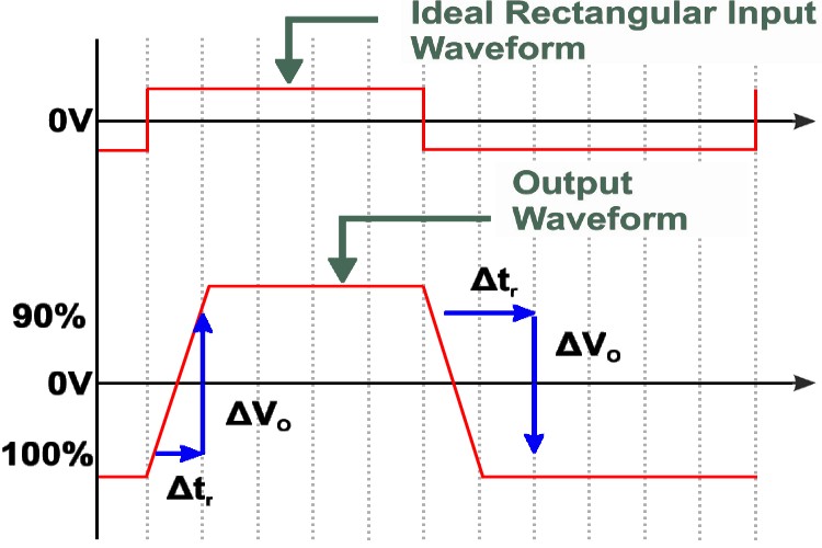
There is a giant block of text in the "Slew rate limiting" that readers probably skip over because it is long and dense with lots of numbers. I suggest deleting most of the text starting from "Consider, for example, an op amp configured for a gain of 10. Let the input be a 1 V, 100 kHz sawtooth wave..." and replace it with a simple picture showing the output of a slew-rate limited opamp to a rectangular input, with a horizontal Δv and vertical Δt line marked on the slewed output and with a diagonal indicating the slewed slope Δv/Δt (maybe something like https://components101.com/sites/default/files/inline-images/output-response.jpg but better). Em3rgent0rdr (talk) 22:53, 17 November 2025 (UTC)
- hm, I think that text (and the figure) is a bit hm, problematic. Starts with that it's physically impossible to get a sharp rectangle wave, that the edge then gets distorted through input impedances, takes a brief detour through Gibbs phenomenon… and if someone really connects their high-speed signal generator to an opamp (say, in unity gain buffer configuration), to their high-speed oscilloscope to see any of this, they'd think everything they've learned is wrong.
- We should probably use at least something that is continuously differentiable and at least has a voltage slope, i.e., something where "slew rate" is a sensible term to apply to the input signal.
- Quite honestly, why not a sine wave at its zero crossing? The slope of a sine at zero-crossing is just its amplitude times its frequency (easy to show: derivative of sine is cosine, which has its maxima (value=1) where the sine crosses zeros; the rest is just stretching/multiplying), and we get in no trouble with physical possibility in a universe of bounded power, bandwidth limitations, and weird edge effects. MüllerMarcus (talk) 13:18, 21 November 2025 (UTC)
- Have two sinewaves. A low amplitude wave showing no slew rate limiting and a large one with slew rate limiting. Constant314 (talk) 14:18, 21 November 2025 (UTC)
- Ok, two sine waves sounds good. I wired up a simple voltage buffer using a MCP6004 opamp, and took screenshots with two inputs, one with a 500 kHz 0.5 volt(peak) sine that is just under the limit of this particular chip (the data sheet says 0.6 V/µs, but the actual specimen seems to be a bit better at 0.75 V/µs), and again with a 1-volt(peak) sine that is slew limited and turns into a triangle wave. My oscilloscope and breadboard seem a bit noisy. I'll wait a few days before making an edit to see if someone comes up with a better example.

Output of a MCP6004 configured as a voltage buffer with an input 500 kHz 0.5-volt(peak) sine. The maximum slope of the sine is about 650mV per microsecond, which is less steep than the opamp's maximum slew rate, so the buffered sine isn't distorted. 
Output of a MCP6004 configured as a voltage buffer with an input 500 kHz 1-volt(peak) sine. The opamp can't transition faster than 750mV per microsecond, causing the sine to be slew-limited and output as a triangle wave. - Em3rgent0rdr (talk) 03:08, 22 November 2025 (UTC)
- I would suggest reducing the amplitude of the slew rate limited signal so that the peaks are rounder. Also, I would want to see the input signal. Constant314 (talk) 07:10, 22 November 2025 (UTC)
- What about this animation?

An opamp's slew limit may distort its output. A 250 kHz sine input (magenta) is fed into an opamp voltage buffer with a ~720 mV per microsecond slew limit. With a small input (400 mV amplitude sine in the first frame), the output (yellow) has almost no distortion. But as the input's amplitude is increased (750 mV in the final frame), the opamp can't transition fast enough to reproduce the larger sine's steeper slope, so the output gets slew limited and is distorted to look more like a triangle wave. - Em3rgent0rdr (talk) 19:08, 22 November 2025 (UTC)
- I like it. Constant314 (talk) 20:04, 22 November 2025 (UTC)
- A pause at the end would be good. Constant314 (talk) 20:05, 22 November 2025 (UTC)
- ok done...I've set the gif to wait 5 seconds at the final frame now, and also labeled the ΔV and Δt for that final frame. Em3rgent0rdr (talk) 05:27, 23 November 2025 (UTC)
- A pause at the end would be good. Constant314 (talk) 20:05, 22 November 2025 (UTC)
- It's so good! Thanks! MüllerMarcus (talk) 16:29, 30 November 2025 (UTC)
- I like it. Constant314 (talk) 20:04, 22 November 2025 (UTC)
- I would suggest reducing the amplitude of the slew rate limited signal so that the peaks are rounder. Also, I would want to see the input signal. Constant314 (talk) 07:10, 22 November 2025 (UTC)
- Have two sinewaves. A low amplitude wave showing no slew rate limiting and a large one with slew rate limiting. Constant314 (talk) 14:18, 21 November 2025 (UTC)


MOSFET OP AMPS
The statement copied below is incorrect. Mosfet amps exist but are not common. MOSFET transistors are noisy and drift.
"1970: First high-speed, low-input current FET design. In the 1970s, high-speed, low-input current designs started to be made by using JFETs. These would be largely replaced by op amps made with MOSFETs in the 1980s." MervinFerd2026 (talk) 01:27, 29 May 2026 (UTC)
- @MervinFerd2026: Thanks for the report. I can't assess the accuracy of that section which was added (diff), without references, in 2008 by someone who last edited in 2015. The simplest probably would be to edit the section and remove any dubious claims that are unreferenced. Please have a go. Johnuniq (talk) 05:25, 29 May 2026 (UTC)
Content Disclaimer
Informasi ini disarikan dari Wikipedia dan disajikan kembali untuk tujuan edukasi. Konten tersedia di bawah lisensi CC BY-SA 3.0. Kami tidak bertanggung jawab atas ketidakakuratan data yang bersumber dari kontribusi publik tersebut.
- The information displayed on this website is sourced in part or in whole from Wikipedia and has been adapted for the purpose of restating it. We strive to provide accurate and relevant information, however:
- There is no guarantee of absolute accuracy. Wikipedia is an open, collaborative project that can be edited by anyone, so information is subject to change.
- It is not intended to constitute professional advice. The content displayed is for informational and educational purposes only. For important decisions (e.g., medical, legal, or financial), please consult a professional.
- Content copyright. Wikipedia is licensed under the Creative Commons Attribution-ShareAlike License (CC BY-SA). This means that content may be reused with appropriate attribution and shared under a similar license.
- Responsible use. Any risk arising from the use of information from this website is entirely the responsibility of the user.